My stacking rig

Have questions about the equipment used for macro- or micro- photography? Post those questions in this forum.

Moderators: rjlittlefield, ChrisR, Chris S., Pau

LSRasmussen
Posts: 67
Joined: Mon Apr 14, 2008 9:21 am
Location: Denmark
Contact:

My stacking rig

Post by LSRasmussen »

Hello all,

As promised here's a picture of my new stacking rig. I'm still planning additional changes such as mounted lightsources etc. Comments or suggestions are very welcome !

Image

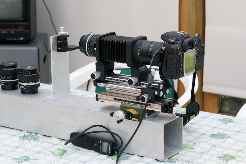
As you can see I've opted for the move camera option. This is mainly due to having the movement controls where it feels right ! The base is a 10 by 10 cm aluminium profile with 4mm thick walls. It seems plenty sturdy and stable, but I still have to check for vibrations at long shutter times.

Thanks for looking,

Lars

lauriek
Posts: 2402
Joined: Sun Nov 25, 2007 6:57 am
Location: South East UK
Contact:

Post by lauriek »

That looks like the basis of a pretty solid rig to me, my only concern would be the bellows mounted at only one point. I find I need to brace underneath my bellows front and back to avoid any 'tipping' of the camera side of things... I would be inclined to balance this by wedging something (a piece of wood?) underneath the front of the bellows...

rjlittlefield
Site Admin
Posts: 23626
Joined: Tue Aug 01, 2006 8:34 am
Location: Richland, Washington State, USA
Contact:

Post by rjlittlefield »

I agree with Laurie. You have a good looking rig, but it would be a lot better to nail down the front of that bellows.

What I used to do was run my tripod mount full forward on the bellows, than either wedge under the rear end or actually bolt the camera separately to the table (see here. Then one day it occurred to me that I had a spare bellows and I could move its tripod mount onto the first bellows to provide a second mounting point.

Your setup is similar enough to mine that you can see why camera orientation would matter. Once you nail down the front of your bellows, your rig will be rigid against up/down movements of the camera. But side/side movements will be resisted only by torsion through that whole chain from the bellows on down. It's a lot less rigid in that direction.

--Rik

puzzledpaul
Posts: 414
Joined: Sun Aug 06, 2006 4:15 am
Location: UK
Contact:

Post by puzzledpaul »

Although I've not done any stacking (and therefore no actual experience) I think I'd consider removing the tripod mount part of the bellows completely - as it's probably duplicating the travel obtainable from the machining table ... and if so, redundant ...

... and also maybe filling the ali box section with something like sand (or similar) with a couple of (wooden?) end caps to increase overall mass and lower the c of g.

Maybe also attach a crossbar at the 'business end' of the ali box too, so you end up with a 'T' shape (in plan view) - which would then allow for 3 point mounting - rather than relying on two 'flat' surfaces (box section underside / tabletop) to 'seat where they touch'

pp
Boxes, bottlebottoms, bits, bobs.

augusthouse
Posts: 1195
Joined: Sat Sep 16, 2006 1:39 am
Location: New South Wales Australia

Post by augusthouse »

Hi Lars,
I'm just wondering about the levels. Have you put a spirit-level on the table that your rig is sitting on. Is there anything in the room that might cause vibration, like a fridge.

An optical breadboard/baseplate would also make a good base and allow secure attachment of additional components.

Craig
To use a classic quote from 'Antz' - "I almost know exactly what I'm doing!"

LSRasmussen
Posts: 67
Joined: Mon Apr 14, 2008 9:21 am
Location: Denmark
Contact:

Post by LSRasmussen »

Hi all,

Thanks for all the replies and suggestions. I'm now working on "stiffening" the setup in order to reduce possible vibrations. The suggestion about a crossbar on the specimen stage, was right on the money as I've identified that particular L design as being prone to vibrate. With respect to levelling,
until now I've been using it on my normal work table (With running PC and all !) which is probably not a good thing. For the next image I will locate the rig directly on my floor (concrete) and make sure it's properly aligned.

The only remaining issue (when the above fixes has been implemented) will be the fact that my camera is not supported from below. It's "hanging" from the Bellows by means of a PK13 tube and the TC 201 tele converter. I have not identified a way to support the camera as it's moving when focussing. I do realize that I could make a custom support that would rest on the back part of the bellows rails, however that would seriously limit the bellows ability to extend.

Also, puzzledpaul suggested to remove the bottom part (bellows focussing stage) from my setup. Well, I'm really using the functionality as it allows very fast focussing. It makes it a lot easier to get the specimen in focus and ready for stacking so I think I'm going to keep it in place.

Again, thanks everybody for you excellent advice !

//Lars

lauriek
Posts: 2402
Joined: Sun Nov 25, 2007 6:57 am
Location: South East UK
Contact:

Post by lauriek »

Lars, out of interest, from your setup, what is that box section aluminium's 'proper' use - ie where should I go to try to purchase some? Cheers!

I'm using an old wooden sink cover as my base atm, I reckon vibration should be higher frequency and die out quicker with an aluminium base...

lauriek
Posts: 2402
Joined: Sun Nov 25, 2007 6:57 am
Location: South East UK
Contact:

Post by lauriek »

I shoot my rig on the floor - not concrete unfortunately, and I have to watch out for people walking past (well my Mrs!) - this is on floorboards but when working at high mag, with some tiny detail focused on the live view screen, you should see the subject waggle about the place when someone does walk past, it's shocking!

Do you really need all that extension (and the TC)? I would have thought with a 25mm lens, all that would be rather too much! What's the maximum extension of your bellows? If the camera was mounted straight on the back of the bellows I reckon you would have less of an issue with all that weight hanging off the back of a big lever!

LSRasmussen
Posts: 67
Joined: Mon Apr 14, 2008 9:21 am
Location: Denmark
Contact:

Post by LSRasmussen »

lauriek,

I'm afraid I've had this particular alu profile sitting in my garage for a very long time... Probably 20 years or so. I simply cannot remember how I got hold of it or what it originally was intended for. I'm just glad that I finally found a use for it ! I'm one of these people that never throw things away as they might just come in handy someday ! ;-)

The extended bellows in the picture is just for show. In my latest ant picture, the bellows were not extended at all. The maximum extension of the PB4 bellows is 14.5 cm. It's true that I could ditch the TC 201 tele converter and I'm certainly going to try in order to see if I get any improvement in IQ. However the PK 13 is required in order to mount the D200 due to the fact that the PB4 is not designed for the D200 form factor. Without the PK13, mounting the camera is very difficult and also potentially dangerous due to the possibility of damaging the camera autofocus contacts.

It's going to take me a while to get through all the permutations of lenses, TC's and bellow extensions plus the various lighting options ! But that's exactly where all the fun is located ! ;-)

//Lars

DaveW
Posts: 1702
Joined: Fri Aug 04, 2006 4:29 am
Location: Nottingham, UK

Post by DaveW »

One method I read of making a cheap anti-vibration platform used to be an inflated car tyre inner tube (pre tubeless tyres) with a couple of concrete paving slabs placed on top. The inner tube absorbed any vibrations from the ground since the weight of the concrete slabs provided inertia and was difficult to start moving or vibrating.

DaveW

Planapo
Posts: 1583
Joined: Tue Nov 07, 2006 2:33 am
Location: Germany, in the United States of Europe

Post by Planapo »

Hello Lars,

good to see that someone uses this milling table the way I intend to use mine, i.e. for moving the bellows/camera and not the subject.
I had thought to have my bellows screwed onto a metal board by a counter-sunk screw and then fasten this board to the milling table with those stepped clamping jaws that come with it. But you seem to have managed to mount your bellows directly onto the table.
I would be interested how you´ve accomplished this with the - presumably - blind tapped hole(s) on the underside of the bellows?

--Betty

LSRasmussen
Posts: 67
Joined: Mon Apr 14, 2008 9:21 am
Location: Denmark
Contact:

Post by LSRasmussen »

Hi Betty,

It is indeed possible to mount the PB-4 bellows directly to the Proxxon milling table. I used two of the sqare nuts that came with the milling table and 2 screws from my junkbox (They need to be correct in length, otherwise they can damage the milling table). By moving the bellows section forward, you can access the holes in the focussing stage (used for attaching the bellows to a tripod). I simply inserted one screw in the middle hole and the other in the forward hole, turned the PB-4 around and attached the nuts. You can then slide the PB-4 into the middle grove of the milling table. Once in place, just tighten the screws and you're up and running.

Hope this helps !

//Lars

Planapo
Posts: 1583
Joined: Tue Nov 07, 2006 2:33 am
Location: Germany, in the United States of Europe

Post by Planapo »

Thanks Lars!
Now I see and know how you did it, and that the holes on that PB-4 bellows go through, whereas the holes on the bellows I am familiar with are tapped blind holes that are only accessible from the underside.

Seems for my bellows I have to stick to the more laborious way.

--Betty

Post Reply Previous topicNext topic