Stepping your Stage?

Have questions about the equipment used for macro- or micro- photography? Post those questions in this forum.

Moderators: rjlittlefield, ChrisR, Chris S., Pau

ChrisR
Site Admin
Posts: 8662
Joined: Sat Mar 14, 2009 3:58 am
Location: Near London, UK

Stepping your Stage?

Post by ChrisR »

In Chris Slaybaugh's thread on his marvellous rig, the question of automating a focus mechanism was raised. It seems something of a different subject so I started a new thread, Several folk on the forum have had a go, or would wish to. Perhaps we could pool our thoughts and discoveries.

Though I'm considering it I don't have a motorized stage, so I'm not an expert! These are the basics though I've picked up so far:

There are two obvious main ways to go.
A) Move the camera/lens. (I've only seen anyone move camera and lens together, rather than just one, though that would be possible.) One advantage of this approach is that the lighting doesn't move, through the stack. Though microscope focus blocks can be used, a good solution is something like the Proxxon milling table - as first mentioned by Betty planapo! :wink:
http://www.proxxon-direct.com/acatalog/ ... _kt70.html (1mm/rev)

B) Move the subject. Though this could be done using other mechanisms, adjustment of the focus on a microscope is an elegant method. (Typ 0.2mm/rev) This is used by Saphicon with their rather neat stepper units.
http://www.saphicon.com/focus-drive-integrated-s.htm (Approx $1300)

As far as I can see, at the extremes, method A) is more suited to lowest magnifications, and B) highest, though there's considerable overlap. Surely the best place for a microscope focus block, from the point of view of rigidity, is on a microscope?

The amount of fine-focus travel is very important to prevent the need to "back-up" the coarse focus mechanism. Some microscopes' fine focus travel is only 150 micrometer(micron), though common Olympus ones are 30mm, and some (which?) Nikon ones approx 70mm.

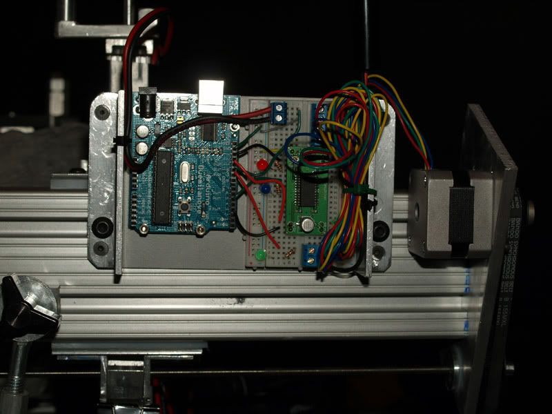
Once you have your motorized mechanism, you have to control it. The most obvious way is to use a microcontroller or PC. If you've never done programming at all, that's a steep learning curve.


As something to play with, I bought a stage and motor s/h for $50. To my surprise it has a 6:1 gearbox between the motor and stage drive, so on a 0.5mm leadscrew gives 26nm per 1/16th microstep. A lot of steps to cover its 50mm, I wonder how it'll behave. Time, energy and metalwork I can't currently do, come between me and its use.
(The vendor may have more, if interested, let me know).

elf
Posts: 1416
Joined: Sun Nov 18, 2007 12:10 pm

Post by elf »

I use method C: :) only the camera moves in my setup.

The subject sits on a stage with 4 axes. The X, Y, and Z axes can be controlled in .00625mm increments which is more than adequate for the magnifications I'm currently working with. The rotation axis is currently manual.

Here's a quick snapshot of the controller and stepper motor:
Image

The microcontroller is an Arduino board with an EasyDriver stepper controller. This is the first hardware project that I've ever done and I was quite surprised by how easy it actually was. I am fairly comfortable programming in C# and the Arduino uses C++ which is pretty close, but not quite as easy. There are several active forums with lots of helpful people. I had a couple of problems that were answered within an hour of posting. The Arduino is open source and there is a ton of code available for it.

I chose to use the microcontroller because of deficiencies in the Olympus SDK. It requires each image to be downloaded to the computer before the next one can be taken. My e330 requires 20+ seconds to do this. Even a small panorama was taking 4 or 5 hours of just shooting. Triggering an IR remote with the microcontroller means the images are stored on the memory card and I can shoot at 8 seconds per frame. The other advantage to using a microcontroller is they are closer to being a real-time system, that is the CPU doesn't get bogged down looking for viruses or doing other things while you're shooting a stack. This can be a big deal if you're going to shoot focus stacked animations. See this thread for one person's journey into macro automation: http://www.timescapes.org/phpBB3/viewto ... dfb7f1066e


There's still quite a bit of cleanup work to do before the entire setup is ready for presentation {-(

In order to add the stepper motor, the mounting plate for the leadscrew had to be enlarged and the lead screw had to be extended a bit. I chose to use a belt drive because it is more tolerant of alignment problems and I can easily change the gear ratio if I need more torque or speed.

The benefits I've seen so far are:
  • Accuracy in step increments
    Tedium relief
    Faster
    Less vibration
If I were going to add a stepper motor to a more traditional setup like AndrewC's or Chris S', I would do the following:
  • Detach the lens mount from the bellows rail and mount it in a fixed position just in front of its previous position on the bellows rail.
    Mount the bellows on a crossslide.
    Use the stepper motor to control the camera racking knob on the bellows rail by replacing the knob with a suitable sized timing belt pulley. The only hard part is building the stepper motor mount.
This will allow shifting the camera left and right to do single row panoramas perhaps 3 or 4 images wide. Adding a z axis with 25-30mm of travel would give you a nice 3x3 pano capability, which with 100 image deep stacks would require 900 images.

Another benefit is the individual steps when moving just the camera are much larger than moving the camera/lens or subject so they can be more accurate.

AndrewC
Posts: 1436
Joined: Thu Feb 14, 2008 10:05 am
Location: Belgium
Contact:

Post by AndrewC »

My setup has a stepper drive thankyou very much :) Actually it has two and at one time did xyz for positioning as well as stacking but I robbed some of the drives for another project.

I'm actually toying with the idea of going back to automated xy movement to make some panoramas at high mag but as I don't have a need for images greater than a 1000px it isn't high on my priorities. For uscope objectives >10x I think they appear telecentric (Rik - you posted something about that I think ?) so you don't need to rotate around the pupil but can just xy linear scan.

See this thread for a discussion on stepper motors: http://www.photomacrography.net/forum/v ... ht=stepper

If you want to automate a "Betty stage" just search the web for CNC Proxxon MF70 conversion
rgds, Andrew

"Is that an accurate dictionary ? Charlie Eppes

rjlittlefield
Site Admin
Posts: 23543
Joined: Tue Aug 01, 2006 8:34 am
Location: Richland, Washington State, USA
Contact:

Post by rjlittlefield »

AndrewC wrote:For uscope objectives >10x I think they appear telecentric (Rik - you posted something about that I think ?) so you don't need to rotate around the pupil but can just xy linear scan.
That's correct from a practical standpoint. Just turn off scaling adjustment in the alignment parameters. If your focus rig is stable enough, turn off alignment altogether.

From a theoretical standpoint, what's going on is a bit more complicated. These lenses are not nearly telecentric. However, they have so little DOF that it's OK to ignore scaling. In fact, it's preferred to ignore scaling because several other optical factors often conspire to make it look like there were big scale changes when in fact there were not. If you leave scaling turned on, it's very easy for example to get unrealistically bulging bug eyes because the closest few frames (in the middle of the eye) look to the software like they need to be scaled larger when they really don't.

In any case, once you've turned off scaling, you've essentially imposed orthographic projection, just like a telecentric lens would do optically, and with orthographic projection, there's no need to rotate around the entrance pupil in order to do stack-and-stitch.

--Rik

Chris S.
Site Admin
Posts: 4037
Joined: Sun Apr 05, 2009 9:55 pm
Location: Ohio, USA

Post by Chris S. »

Excellent idea, Chris R., to separate this discussion out into a different thread. Much needed. (And sorry it's taken me so long to add my two cents.)

Elf, your advice to separate my lens from the camera movement is interesting, but I'm not sure I see the point if I don't want to stitch panoramas. And with the microscope objectives I'm using, I would doubt the image circles would be big enough to permit much horizontal or vertical camera movement. Would I gain enough in not having the entrance pupil move during just a Z-stack to make it worth doing? I understand your point about the camera movements being larger, and therefore more fault tolerant, with this approach, but I'm already doing manual movements of a single micron with no problem, and could probably go smaller--so am not sure what I would gain here. Please feel free to set me straight!

I like Elf's idea about using a belt drive for my focusing block, but in my quick perusal of timing gears (something I know rather little about), so far, the maximum number of gear teeth I've seen has been only a bit above 30. I'd want something in the 400-tooth range at least, wouldn't I? That is, unless I concocted some kind of gearing to make up for it?

For those who use Arduino boards to control their stepper motors, can an Arduino be controlled real time from a PC, or do you constantly have to use the PC to program the Arduino, and then run things from the Arduino?

I ask this because I want a PC-centric approach. I already tether my rig to a PC. Wouldn't want to live without tethering--nothing like being able to check focus, lighting, composition, etc. on a big screen, and the low-powered, dedicated PC wirelessly transfers the images to the much more powerful PC that does the stacking and Photoshop work. Am not worried about things like virus scans happening during stacking, because these services are very easy to supress and restore with a simple bat file.

What I'm looking for is the ability to control focus stepping and camera actuation from a single PC interface, which I assume I can program in Visual Basic (yeah, I know it's a dinosaur, but I know it a bit and it should handle this).

Lastly, does anybody have experience with these folks: http://pc-control.co.uk/osc/ ? They are selling 1.8 degree stepper motors, and I think I want a microstepper, but their control boards seem pretty nifty.

Thanks much!

--Chris

elf
Posts: 1416
Joined: Sun Nov 18, 2007 12:10 pm

Post by elf »

Chris S. wrote: Elf, your advice to separate my lens from the camera movement is interesting, but I'm not sure I see the point if I don't want to stitch panoramas. And with the microscope objectives I'm using, I would doubt the image circles would be big enough to permit much horizontal or vertical camera movement. Would I gain enough in not having the entrance pupil move during just a Z-stack to make it worth doing? I understand your point about the camera movements being larger, and therefore more fault tolerant, with this approach, but I'm already doing manual movements of a single micron with no problem, and could probably go smaller--so am not sure what I would gain here. Please feel free to set me straight!
Separating the lens from the camera will give you orthographic stitches which are limited by the image circle. These are guaranteed to have no parallax. On my BD Plan 10 and 4/3rds sensor, this appears to be at least a 3X3 matrix. Rotating around the entrance pupil doesn't have any limitation so it's possible to do 360 degree panos. With the microscope objectives, I don't think the entrance pupil is close enough to the lens to use this method. I haven't looked at any other higher powered optics to see where the entrance pupil is located. You can also do orthographic stitches by moving the subject or camera/lens horizontally, but this will always have a little parallax. If small individual steps are taken, the parallax can probably be easily disguised in the final image.
Chris S. wrote: I like Elf's idea about using a belt drive for my focusing block, but in my quick perusal of timing gears (something I know rather little about), so far, the maximum number of gear teeth I've seen has been only a bit above 30. I'd want something in the 400-tooth range at least, wouldn't I? That is, unless I concocted some kind of gearing to make up for it?
It's the gear ratio that matters. MXL timing gears are available from 10 grooves to 130 grooves: https://sdp-si.com/eStore/Direct.asp?GroupID=218 . Combine these with a microstepping controller and you will have 20800 steps per revolution, but it will be incredibly slow. :smt028
Chris S. wrote: For those who use Arduino boards to control their stepper motors, can an Arduino be controlled real time from a PC, or do you constantly have to use the PC to program the Arduino, and then run things from the Arduino?

I ask this because I want a PC-centric approach. I already tether my rig to a PC. Wouldn't want to live without tethering--nothing like being able to check focus, lighting, composition, etc. on a big screen, and the low-powered, dedicated PC wirelessly transfers the images to the much more powerful PC that does the stacking and Photoshop work. Am not worried about things like virus scans happening during stacking, because these services are very easy to supress and restore with a simple bat file.

What I'm looking for is the ability to control focus stepping and camera actuation from a single PC interface, which I assume I can program in Visual Basic (yeah, I know it's a dinosaur, but I know it a bit and it should handle this).

Lastly, does anybody have experience with these folks: http://pc-control.co.uk/osc/ ? They are selling 1.8 degree stepper motors, and I think I want a microstepper, but their control boards seem pretty nifty.

Thanks much!

--Chris
No reason you can't control the steppers directly from the PC. I chose the Arduino because of the severe limitations of tethering Olympus cameras and it also gives the opportunity to use it in the field. Small, inexpensive netbook computers probably negate the last advantage. There should be lots of code samples available online. The microcontrollers usually require C++ which is a pretty big jump from VB.

And, yes you want a microstepping controller to drive the 1.8 degree/step motor.

ChrisR
Site Admin
Posts: 8662
Joined: Sat Mar 14, 2009 3:58 am
Location: Near London, UK

Post by ChrisR »

If you're using interpreted VB, as opposed to compiled C (or C++) I'd be wondering about the speed you can achieve at the motor.
As someone equally inept at both,( though have used them for a living), I wouldn't worry about shifting between VB and C. The syntax is different, but loops and arrays and subroutines are still the same. I wonder if there's a Java option...

A second, say, to move between steps isn't an issue, but if you want to move your stage from one end of the stack to the other to check things, 100 seconds would be a pain.
If you used a driver where the stepping versus micro stepping were programmable, you could make it "change gear" to go faster, but I haven't seen one where it is, without extra hardware.

It comes back to how coarse your leadscrew or knob, or whatever, adjustment is. Building something with belts looks the hardest way to do it, to me!

Whether to use a PC or "just" a micro-board is a classic strategy question. There's bottom-up or top-down design. With mechanical stuff, it's tempting to "make the motor turn" as a first thing. Others would write the user manual before deciding anything, then use whatever hardware is required.
Certainly, down the line, a nice user-friendly display on a PC would be easier to use.

rjlittlefield
Site Admin
Posts: 23543
Joined: Tue Aug 01, 2006 8:34 am
Location: Richland, Washington State, USA
Contact:

Post by rjlittlefield »

elf wrote:You can also do orthographic stitches by moving the subject or camera/lens horizontally, but this will always have a little parallax.
The part about "will always have a little parallax" is simply not true.

Use of telecentric optics completely eliminates parallax and is an exact solution, no approximations. See HERE for illustration.

Turning off scale and shift adjustment also completely eliminates parallax. Essentially what this does is to computationally impose the same sort of orthographic projection that telecentric lenses provide optically. Turning off scale adjustment is an approximate solution with regard to image quality, since it pretends that there is no scale change within the in-focus slab when in fact there is some unless the optics are telecentric. However, at high magnifications and wide apertures, DOF is so shallow that the approximation has no visible effects.

Turning off scale adjustment can also be used in conjunction with not-quite-telecentric optics to enable parallax-free stitching from linear shifts even at fairly low magnification and narrow apertures. The example HERE shows a case where 1:1 and f/11 would be fine.

--Rik

RogelioMoreno
Posts: 2978
Joined: Fri Nov 20, 2009 11:24 am
Location: Panama

Post by RogelioMoreno »

ChrisR wrote: A second, say, to move between steps isn't an issue, but if you want to move your stage from one end of the stack to the other to check things, 100 seconds would be a pain.
If you used a driver where the stepping versus micro stepping were programmable, you could make it "change gear" to go faster, but I haven't seen one where it is, without extra hardware.
I am trying to build a focus drive system for my Nikon Labophot + Canon EOS XSi to take a series of pictures automatically.

A few days ago I won an auction on eBay of two API P261X (this is a very old model; but with the winning price of less than $20 shipped it is a deal) microstep controller, this controller has the power supply, motor driver and indexer in one unit. API Indexers all utilize a plain English command set called Intelli-Command Language or ICL for short. With the ICL commands I will be able to setup a base speed, maximum speed, acceleration time and deceleration time.

I ordered a Vexta PK266M-02A (NIB $35 shipped) that has 400 steps/rev, may be this motor is a overkill for the system; but it was the 400 steps/rev motor with the Amps/phase close to one of the setting that support the P261X. This motor has a 0.25"(6.35mm) shaft, the Labophot fine focus has a 3mm shaft, I ordered a few 3mm*6.35mm flexible coupler from linearmotionbearings2008 on eBay, if anybody is interested this seller has other sizes.

I am a computer system engineer and I am planning to develop my own program to move the fine focus, take the picture and download the image using the Canon SDK for EOS.

I will let you know about my progress.

Rogelio

rjlittlefield
Site Admin
Posts: 23543
Joined: Tue Aug 01, 2006 8:34 am
Location: Richland, Washington State, USA
Contact:

Post by rjlittlefield »

Rogelio, welcome aboard! :D

We look forward to hearing more about your project.

--Rik

RogelioMoreno
Posts: 2978
Joined: Fri Nov 20, 2009 11:24 am
Location: Panama

Post by RogelioMoreno »

rjlittlefield wrote:Rogelio, welcome aboard! :D

We look forward to hearing more about your project.

--Rik
Rik,

Thank you.

Rogelio

Post Reply Previous topicNext topic