Bridgelux Vero 18 LED high CRI light

Have questions about the equipment used for macro- or micro- photography? Post those questions in this forum.

Moderators: rjlittlefield, ChrisR, Chris S., Pau

Bushman.K
Posts: 162
Joined: Wed Aug 26, 2015 5:49 pm
Location: OR, USA
Contact:

Bridgelux Vero 18 LED high CRI light

Post by Bushman.K »

This is my first posting here and I'd like to share some information about building my own high power, high CRI LED light source for high magnification photography. This is still work-in-progress project, while I already have working assembled unit.

I know, that it's not the most common approach to use constant light source to replace flash, but I decided to go this way by many reasons. My list of requirements was pretty simple:
  • * Good color reproduction. Having long experience with color correction, image manipulation and analysis, I wanted as good result as possible without getting into a trouble with RGB or W+GR multi-LED light.
    * Enough light to get exposures shorter than 1/20 with field of view larger than 5-7 mm (that's what I'm usually working with).
    * Enough light to be able to shoot close-ups in addition to macro (and that's another reason for high CRI).
    * Both portable battery power and wall socket power capabilities.
    * Continuous operation.
I've examined different options of LEDs available on market and found, that Bridgelux Vero 18 LED COB module, p/n BXRC-30H4000-F-03 most likely fits my needs, so I can try building the whole system around it.

Bridgelux specification tells us this:
  • * CRI 97 (typical)
    * 35W power
    * typical current 1050 mA
    * typical voltage ~32 V
There are surprisingly not so much good constant current drivers for 1050 mA, capable to go up to 35 Volts and to use relatively wide range of input voltages. So, I picked Mean Well LDH-45-1050 driver with 9..18 V input voltage range (there are two variants - with wire leads and studs for thru-hole PCB mount).

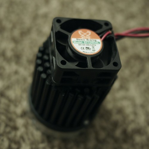
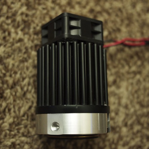
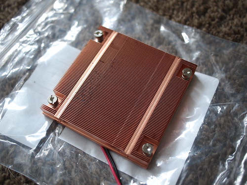
Heatsink is crucial for 35W module to avoid overheating, and it's not that simple to get enough heat removal with passive heatsink. Therefore, I decided to use a bit smaller one than it's required and to add tiny fan to it. I've got noname round pin-type heatsink with 60mm diameter and 50mm height. If there would be anything a bit higher with heat pipes, I would go for it, but for now, I have no other variants. When used for relatively short periods of time (about 2-3 minutes) with long delays (7-10 minutes), current passive cooling setup works fine. For sure, I had to remove anodizing from contact surface and put thermal grease between heatsink and LED.

Fan, (currently - temporary) attached to its rear surface, does its job during continuous operation. It's 40×40×20mm 12 V 70 mA Scythe brand fan (intended for motherboard chipset cooling or something). I can't feed it from LED power bus, because it will interfere with constant current driver, so it should be connected to driver input, not output. To make sure I have nice 12V, I'm using some tiny noname Chinese step-down (buck) converter from eBay, capable to take 4.5..36V and give 0.8...30V (adjustable).

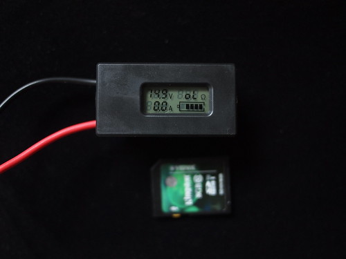
To feed the whole setup, I'm using handmade pack of four rechargeable 26650 cylindrical type Lithium-ion cells 3500 mAh, 3.7 V. They are connected in series. There is no charge gauge currently, but I'm going to add one. They giving more than 12V, therefore, I don't have to use buck-boost converter to feed fan, buck converter is enough. Each battery has overcharge/overdischarge protection circuit built in (batteries are labeled "Protected"), therefore, I don't have to worry about killing them by sucking too much juice from them without having charge gauge - they will just shut off by themselves. It's possible to control charge level by pocket voltmeter.

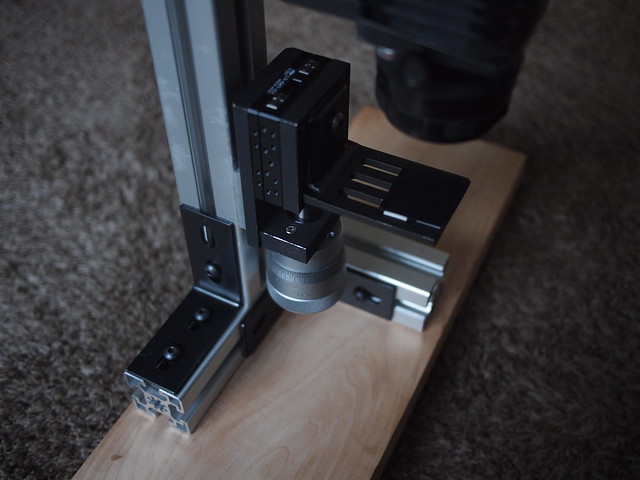
The most tricky part was to make a kind of bracket to hold LED module on the heatsink. Fortunately, I'm a CNC programmer, and I have certain access to machines. So, I designed aluminum bracket in Mastercam and made it of aluminum using Haas CNC vertical mill. Bracket has a pocket for LED with some extra space to compensate for heat expansion, indexing studs to avoid rotation of LED inside it, channel for wires (by the way, I'm using dedicated Molex wiring harness for this LED, available from Digikey and other suppliers), flat portion it its side to accommodate 1/4-20 threaded mounting hole to be able to attach it to standard photo mounting gear. Front side has built-in parabolic reflector, some sort of pocket for protective glass and slots for screws to attach the whole thing to the heatsink. Mounting screws are spring-loaded to compensate for heat expansion of LED thickness too.

I know, that there are factory-made brackets for these LED modules, as well as reflectors, but they look awfully flimsy. My goal was to make it not really rugged, but solid enough to survive hiking trips in my backpack.

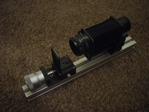
With built-in reflector only, it gives me 110º flood beam. With additional condenser lens (really lousy one, using it just for testing) it goes down to 40º beam. For sure, I'm going to experiment more with focusing system to get narrow spot light (specific suggestions are really welcome).

Here are some pictures.

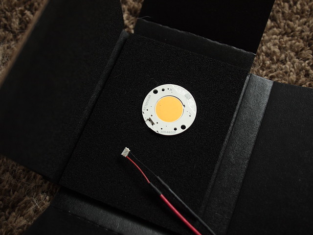
LED module in original package (nice black anti-static foam, by the way) with dedicated Molex wiring harness
Image

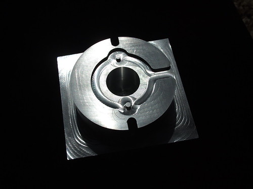
LED bracket after machining back side (LED pocket, indexing studs and wire channel are clearly visible)
Image

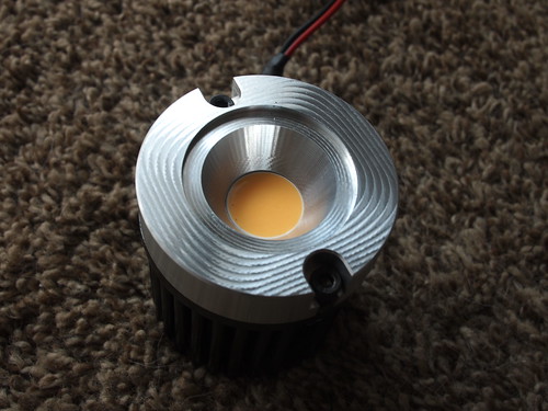
Front side of finished LED bracket (already attached to heatsink)
Image

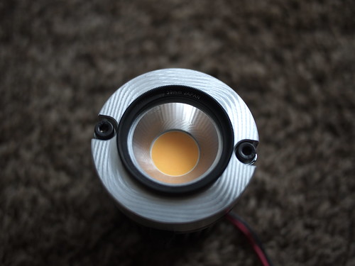
Protective glass filter glued in (I'm using cheap 39mm UV filter - it also gives me an additional mounting option for diffuser, add-on lenses and so on)
Image

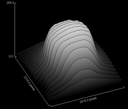
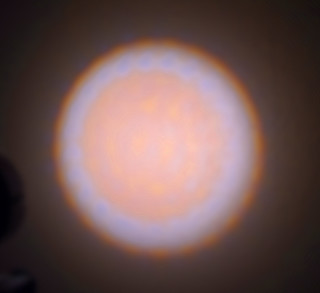
Brightness uniformity test of 40º beam (photo of light spot on uniform white surface was analyzed in ImageJ for intensity)
Image

Four times amplified color non-uniformity test of focused 40º beam. Normally, you can't see this, because color intensity of test photo was intentionally amplified. And it's easy to reduce existing non-uniformity by using focusing system with "wrong" focal point to get certain grade of diffusion on first element.
Image

Power pack with constant current driver assembly. Switch is connected to driver's "disable output" pin to avoid using high current switch. Power pack has XT60 connector (standard for some RC model power packs).
Image
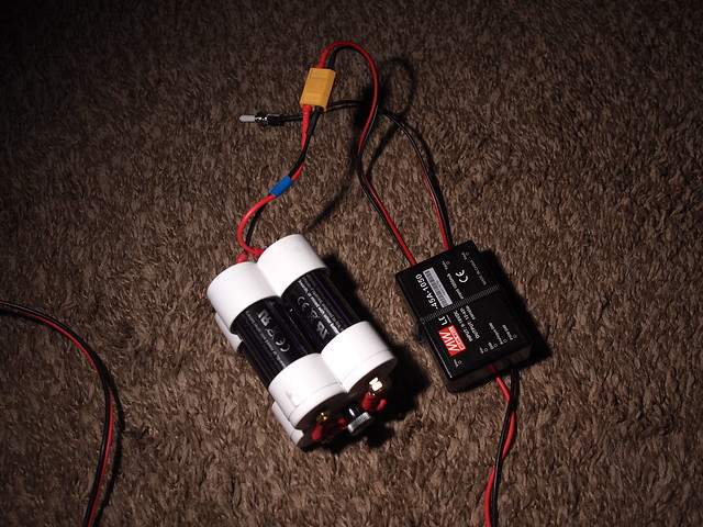
I don't recommend making power packs this way (PVC caps glued together with PVC cement, equipped with spring-loaded contacts and fastened together with threaded rod). I just got 26650 for half price, that's why I'm messing with them. Otherwise, I would use 18650 cells and widely available holders for them.

So, basically, that's all. Feel free to ask any questions.

ChrisR
Site Admin
Posts: 8671
Joined: Sat Mar 14, 2009 3:58 am
Location: Near London, UK

Post by ChrisR »

Way to go :)
A picture of the full heat sink & fan would be nice. I have a couple of Mean Well power supplies. A major UK parts suppplier (RSWWW) used to sell them but appears to have stopped, and they've appeared on eBay - I hope they're ok.

Exposures with bright LEDs should be short, perhaps 125th second, so an obvious thing to do would be dim them between shots, while the Stackshot (etc) is moving. A small timer can turn the fan off just before the shot to avoid vibrations.

I'm surprised (dismayed!) that you had to machine the mount. Charles Krebs found a heatsink which fitted hiis LEDs (long, star section one), so I wonder if something is available for yours.

Bushman.K
Posts: 162
Joined: Wed Aug 26, 2015 5:49 pm
Location: OR, USA
Contact:

Post by Bushman.K »

I will add a picture of heatsink and fan later.

My stacking stage is full manual. I made it by replacing tiny original head with large Starrett micrometer head from optical comparator. It has 0.0001" non-vernier scale and way easier to operate even with single finger than conventional small heads. That's why I'm not even thinking about motorized one. Another reason is I have Olympus E-PL1, and it doesn't have remote shutter control. So, all those features like fan control and dimmer are, probably, something for the future.

Indeed, there are special heatsinks for my module, as well as brackets and reflectors.

But dedicated heatsinks are intended for passive cooling, therefore they are too big. They also have mounting options for those plastic mounting brackets I'll talk about below. Pin-type heatsinks like I used have larger surface than star-shaped ones. Only better solution is thin rib type, but they are usually also too large and fragile.

My custom mounting bracket is much more solid than flimsy plastic ones made by LEDiL, for example. It also works as additional heatsink, and it has built-in reflector for flood light mode being only 13mm thick. So, it probably counts for some advantage comparing to factory-made ones. In addition to that, as I said, I'm CNC programmer, so it doesn't make any problem for me to design and program custom parts. Access to machines is a bit tricky question, but anyway.

Next thing I'm going to try is to make better removable focusing system using more than one condenser lens. That one I'm using is huge, err... breast-shaped one from eBay, and it obviously has ugly side beam and so on.

Bushman.K
Posts: 162
Joined: Wed Aug 26, 2015 5:49 pm
Location: OR, USA
Contact:

Post by Bushman.K »

Pin-type heatsink with 40x40x20mm Scythe brand 12V 70mA fan, view from the rear end
Image

Pin-type heatsink with fan, side view. Mounting threaded hole in LED bracket is also visible here
Image

Fan is attached with industrial strength glue-backed Velcro (hooks on fan, loops on heatsink). This is the easiest way to make it removable and reduce vibration in the same time.

jnh
Posts: 160
Joined: Mon Apr 27, 2015 7:34 am
Location: US East Coast

Post by jnh »

Nice built! I particularly like the custom-machined LED holder. But where did you get the pin-type heat sink?

I recently built some LED lights based on Charles Krebs' design. While looking for LEDs and heat sinks I came across these types of heat sinks, but was unable to find a distributor that would sell them to end users.

Bushman.K
Posts: 162
Joined: Wed Aug 26, 2015 5:49 pm
Location: OR, USA
Contact:

Post by Bushman.K »

Thank you!

I'll try to explain it in details.

Looking for dedicated Bridgelux cooling solutions I found one company, that makes heatsinks and offers complete solutions too, it's called Cooliance http://www.cooliance.com
They actually have fully assembled systems with fan controller built in. But I have no idea where to get them - US distributor online store doesn't work.

But you still can easily purchase passive ones. I've got my 60x50mm heatsink from http://www.newark.com which is US branch of http://farnell.com

Part number for it is CML6001-52-6-101 and originally it's intended for ICs, not for LEDs. And with natural convection they claim it has 3.8ºC/W thermal resistance, which is enough for cooling 16-18W LED in continuous mode at room temperature.

Bushman.K
Posts: 162
Joined: Wed Aug 26, 2015 5:49 pm
Location: OR, USA
Contact:

Post by Bushman.K »

Another addition to my portable power pack:
Image

It's some cheap Chinese indicator you can easily find on eBay by keywords "lithium ion battery meter". Most of them have pictures with bare circuit board, with no hint of this black plastic casing, so you have to use screen as distinctive feature. Costs about $4.

This indicator is capable to measure voltage, current, load internal resistance (I wouldn't trust it) and to display battery charge percentage. Lower and upper voltage limit for charge gauge are programmable, as well as backlight. Didn't have a chance to measure power consumption of it yet.

You don't have to connect load in series with it if you don't want to monitor current.

TheLostVertex
Posts: 318
Joined: Thu Sep 22, 2011 9:55 am
Location: Florida

Post by TheLostVertex »

Very nice project. I always wish I have a cnc mill laying around.

Does the camera you have have a fully electronic shutter, or electronic first curtain shutter? What sort of magnifications are you aiming for with this set-up?
Bushman.K wrote:My stacking stage is full manual. I made it by replacing tiny original head with large Starrett micrometer head from optical comparator. It has 0.0001" non-vernier scale and way easier to operate even with single finger than conventional small heads. That's why I'm not even thinking about motorized one.
Do you have pictures of this somewhere? I have a parker daedel slide and I find it is pretty finicky feeling for anything over 4-5x.

Bushman.K
Posts: 162
Joined: Wed Aug 26, 2015 5:49 pm
Location: OR, USA
Contact:

Post by Bushman.K »

Thank you.
Having an access to real CNC (not one of those 2D DIY routers) is a great thing. I wish I have better access too.

No, my camera doesn't have any of those modern features - it's just very basic Olympus E-PL1, cheapest one from their first generation mirrorless cameras. Only thing I'm using to reduce vibration is two seconds delayed shutter.

Using my current setup, I'm getting magnification about 3-4x, which means horizontal linear field of view about 4-5mm. Current typical step for stacking is 0.005" while I can easily go down to 0.001" or 0.0005" with no problem - large diameter micrometer head works fine.

Here is my stage in vertical (microscope-style) mode
Image

Overview photo without pedestal "legs"
Image

"Shelf" for objects can be easily removed and camera with bellows can be mounted on the translation stage via QR clamp. Stage itself also can be mounted on a tripod, tripod head or QR clamp.

Optical system consists of USSR-made bellows (quite wobbly, if you don't tighten it to death, so I had to add some set screws to make it more rigid) and 50mm Helios lens (also USSR-made, it was a kit lens for Zenit SLRs). Helios is not the best lens ever, definitely, but it works.

I was using this optical system without stacking stage for several years and I'm satisfied with results. Unlike the main part of people, using stacking mainly for insects, I'm more interested in lichens, moss and slime mold. Therefore, it was important for me to make my setup modular and usable in the field, because usually you are not supposed to bring concrete bollard to your home to take photos of nice lichen on it.

Image

Charles Krebs
Posts: 5865
Joined: Tue Aug 01, 2006 8:02 pm
Location: Issaquah, WA USA
Contact:

Post by Charles Krebs »

Very impressive!

That is a lot of light for a 3X-4X set-up (even if diffused). I'll be curious to see what type of exposures you wind up getting. Love the LED "module".

jnh:
But where did you get the pin-type heat sink? .... While looking for LEDs and heat sinks I came across these types of heat sinks, but was unable to find a distributor that would sell them to end users.
Have a look here: http://www.alphanovatech.com/en/cindex5e.html

A huge selection of active and passive heat-sinks, and you can purchase directly from them. (Very well documented as well). I had tried a "pin-type" with a small fan for a high power LED microscope light replacement. I found that these small fans created too much vibration with a hard mounted microscope set-up, probably fine for external lights not directly attached to the "rig". (Perhaps there are some brands that are better in this regard). While they are not particularly noisy, in my small quiet workroom I really disliked the constant noise of these little fans.

Bushman.K
Posts: 162
Joined: Wed Aug 26, 2015 5:49 pm
Location: OR, USA
Contact:

Post by Bushman.K »

Thank you, Charles! And it's good to see other people from Pacific Northwest here.

Yes, that's enough light even for greater magnification, but more is always better. Comparing exposure times I'm getting in tests, this light in flood mode gives the same amount of light as 130W incandescent lamp with built-in reflector I was using before.

Speaking of heatsinks for desktop applications, such as fiber-optic light sources and so on. I've found a kind of "silver bullet": passive thin-rib heatsinks with heat pipes for HP Proliant servers. You can get used one from eBay for less than $10. They are low-profile (0.5"), but quite wide (4x4" or something).
Image

If noise is the only concern regarding of fan, it's easy to eliminate it by using high performance fan throttled down to lower RPM. Sanyo Denki makes really good ones for servers.

TheLostVertex
Posts: 318
Joined: Thu Sep 22, 2011 9:55 am
Location: Florida

Post by TheLostVertex »

Thanks for the photos. The micrometer head looks much larger than the one I have, so I imagine it is a lot nicer to work with.

Bushman.K
Posts: 162
Joined: Wed Aug 26, 2015 5:49 pm
Location: OR, USA
Contact:

Post by Bushman.K »

Micrometer head is DIA 50mm (2"). And, as I said, it's direct reading, so you don't have to break your neck to read vernier scale. Imperial scale models have 0.0001"/2.54microns resolution (rarely - 0.0002"/5.08microns), metric scale models have 0.002mm (2microns) resolution.

These things are available, for example, from BMI Surplus for price from $20 to $300 depending on make, condition and travel (never seen anything below $100 with more than 25mm/1" travel). Some of them can be used as direct replacement for small heads, but you can rarely find one with similar dimensions.

Bushman.K
Posts: 162
Joined: Wed Aug 26, 2015 5:49 pm
Location: OR, USA
Contact:

Post by Bushman.K »

A couple of updates regarding my setup.

- Test of both ugly Chinese condenser lenses with slightly matted film attached to their flat backs was successful: even very subtle matting removes any signs of color non-uniformity caused by LED chips arrangement. So, now I only need some parts to mount them properly.

- Voltage/charge indicator seems to be drawing only 0.6mA - not something to worry about, so I will connect it permanently to constant current power supply input.

Bushman.K
Posts: 162
Joined: Wed Aug 26, 2015 5:49 pm
Location: OR, USA
Contact:

Post by Bushman.K »

Another portion of test results.

Light source was set at ~50mm distance from the object.
To make light spot smaller, I put some noname aspherical plano-convex lens in front of it. (Its thickness is almost equal to its radius.)
Used 58mm f5.6 lens with bellows to achieve 2-3x magnification.
Sensitivity was set to ISO 100.

White surface of lichen requires 1/800
Darker objects such as leaf surface require 1/160..1/400
Tree bark requires about 1/200

These values are not scientific ones, but it gives an idea, how much light does it give. I'm completely satisfied with it.

Using better (but bigger and heavier, which doesn't really fit my picture of portable setup) collimator with two lenses it's possible to get even brighter spot.

Post Reply Previous topicNext topic