
The code looks correct. What is your power supply? Are you using the correct size resistor for the IR LED? As a general question to everyone, will IR LED output be visible in a digital image?
You may want to see if someone on one of the Canon hacker forums knows what the pulse sequence should be.
p.s. If you have a scope, this link could help: http://www.kerrywong.com/2012/08/27/rev ... -protocol/
p.p.s. Is the anode connected to the PWM pin?
How to connect the StackShot to the Canon EOS M3 ?
Moderators: rjlittlefield, ChrisR, Chris S., Pau
-
rjlittlefield

- Site Admin
- Posts: 23621
- Joined: Tue Aug 01, 2006 8:34 am
- Location: Richland, Washington State, USA
- Contact:
Hello Elf,
The power supply is an active USB-hub (Arduino is connected to the computer) .
The white LED works correctly. The light of the IR-LED I have checked with a camera in live-view mode.
So, the IR-LED works too. And my Canon Eos 6D works correctly with the RC-1 without any problem.
So, I have a problem with the software (pulse sequence for the Canon 6D ).
BR, Adi
-
rjlittlefield
- Site Admin
- Posts: 23621
- Joined: Tue Aug 01, 2006 8:34 am
- Location: Richland, Washington State, USA
- Contact:
Are you saying that you're unable to capture an image showing the light of the IR-LED? If so, then I find that very puzzling. The same camera sensor and optics are being used in both cases. I just now checked, and my cell phone and Canon A710 had no trouble capturing images with the IR light on my TV remote shining brightly. It is just a matter of making sure that the exposure is made while the LED is shining at least part of the time. In my test this was done by holding the Mute button continuously while clicking the camera's shutter button. Both cameras captured the light on the first attempt.Adalbert wrote:I only can see the light of the IR-LED on the display of the film-camera or photo-camera in live-view mode.
--Rik
I'd be more inclined to say the problem was in the LED. The RC-1 has been around for about 10 years, so the pulse sequence in the multi-camera-ir software should be correct.Adalbert wrote:Hello Elf,
The power supply is an active USB-hub (Arduino is connected to the computer) .
The white LED works correctly. The light of the IR-LED I have checked with a camera in live-view mode.
So, the IR-LED works too. And my Canon Eos 6D works correctly with the RC-1 without any problem.
So, I have a problem with the software (pulse sequence for the Canon 6D ).
BR, Adi
Hi Rik,
Yes, I can capture an image of the IR-LED too.
The sketch for the IR-controller uses the pulses of some milliseconds :-)
So, I have changed the sketch and could capture an image.
Now, I’m trying to implement the following idea:
http://www.doc-diy.net/photo/eos_ir_remote/
The current sketch looks like that:
Unfortunately it doesn’t work  but I can see the blinking IR-LED in the display :-)
BR, Adi
Yes, I can capture an image of the IR-LED too.
The sketch for the IR-controller uses the pulses of some milliseconds :-)
So, I have changed the sketch and could capture an image.
Now, I’m trying to implement the following idea:
http://www.doc-diy.net/photo/eos_ir_remote/
The current sketch looks like that:
Code: Select all
// ARDUINO NANO CANON RC-1 infrared remote control
#define F_CPU 16000000L // 16 MHz
#include <util/delay.h> // from arduino library
#define NPULSES 16
#define HPERIOD 0.01524
#define INSTANT 7.33
#define DELAYED 5.36
void setup()
{
pinMode( 5, OUTPUT); // for IR-LED on data 5
pinMode(13, OUTPUT); // for TEST-LED on data 13
}
void loop()
{
// asm volatile ("nop");
// asm volatile ("nop");
/***************** INSTANT MODE ****************************/
digitalWrite(13, HIGH); // set the test LED to ON
for(int i=0; i<NPULSES; i++)
{
digitalWrite( 5, HIGH); // set IR-LED to ON
_delay_ms(HPERIOD);
digitalWrite( 5, LOW); // set IR-LED to OFF
_delay_ms(HPERIOD);
}
_delay_ms(INSTANT); // _delay_ms(7.33); // instant mode
for(int i=0; i<NPULSES; i++)
{
digitalWrite( 5, HIGH); // set IR-LED to ON
_delay_ms(HPERIOD);
digitalWrite( 5, LOW); // set IR-LED to OFF
_delay_ms(HPERIOD);
}
digitalWrite(13, LOW); // set the test LED to OFF
/***************** END OF INSTANT ****************************/
_delay_ms(5000); // 5 seconds delay
/***************** DELAYED MODE ******************************/
digitalWrite(13, HIGH); // set the test LED to ON
for(int i=0;i<NPULSES;i++)
{
digitalWrite( 5, HIGH); // set IR-LED to ON
_delay_ms(HPERIOD);
digitalWrite( 5, LOW); // set IR-LED to OFF
_delay_ms(HPERIOD);
}
_delay_ms(DELAYED); // _delay_ms(5.36); // delayed mode
for(int i=0;i<NPULSES;i++)
{
digitalWrite( 5, HIGH); // set IR-LED to ON
_delay_ms(HPERIOD);
digitalWrite( 5, LOW); // set IR-LED to OFF
_delay_ms(HPERIOD);
}
digitalWrite(13, LOW); // set the test LED to OFF
/***************** END OF DELAYED MODE **************************/
_delay_ms(5000); // 5 seconds delay
}
BR, Adi
Everything I know about electronics, I learned on the Internet, so here's a couple of sites that should explain what you need better than I:
http://www.analysir.com/blog/2014/10/03 ... duino-pin/
http://electronics.stackexchange.com/qu ... th-arduino
http://www.analysir.com/blog/2014/10/03 ... duino-pin/
http://electronics.stackexchange.com/qu ... th-arduino
Hello Elf,
Many thanks for the links!
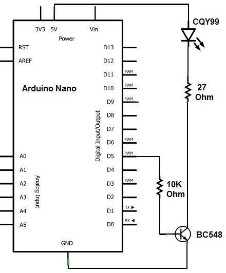
I have already tried with the transistor and then with an external power supply 8V.
Like follows but with the resistor 27 Ohm:
http://www.analysir.com/blog/2015/10/12 ... sing-uart/
I only was able to see the blinking IR-LED in the display of IXUS 6.
But it didn’t trigger the CANON EOS 6D. Probably something is wrong with this LED.
Probably I will have to use a LED like SFH484 with 880 nm (instead of 950nm).
BTW, as soon as I have the RC-6 I will try with its IR-LED.
BR, Adi
Many thanks for the links!
I have already tried with the transistor and then with an external power supply 8V.
Like follows but with the resistor 27 Ohm:
http://www.analysir.com/blog/2015/10/12 ... sing-uart/
I only was able to see the blinking IR-LED in the display of IXUS 6.
But it didn’t trigger the CANON EOS 6D. Probably something is wrong with this LED.
Probably I will have to use a LED like SFH484 with 880 nm (instead of 950nm).
BTW, as soon as I have the RC-6 I will try with its IR-LED.
BR, Adi
Hello Elf,
I have already tested my ir-controller with the 880nm LED but without success
So, I have looked for the pulse-frequencies in a loop and found out that it works between 7 and 10 micro seconds (with 880nm and 950nm too :-)
BR, Adi
I have already tested my ir-controller with the 880nm LED but without success
So, I have looked for the pulse-frequencies in a loop and found out that it works between 7 and 10 micro seconds (with 880nm and 950nm too :-)
Code: Select all
for(int i=0; i<16; i++)
{
digitalWrite(9, HIGH);
delayMicroseconds(j); // j = between 7 and 10 micro seconds !
digitalWrite(9, LOW);
delayMicroseconds(j);
}
delayMicroseconds(7330);
for(int i=0; i<16; i++)
{
digitalWrite(9, HIGH);
delayMicroseconds(j);
digitalWrite(9, LOW);
delayMicroseconds(j);
}