Design of a new LED flash module.

Have questions about the equipment used for macro- or micro- photography? Post those questions in this forum.

Moderators: rjlittlefield, ChrisR, Chris S., Pau

fotoopa
Posts: 194
Joined: Sat Dec 14, 2013 3:14 am
Location: Belgium
Contact:

Design of a new LED flash module.

Post by fotoopa »

I have already made ​​a LED flash. Now I would like to build a better version. The biggest problem is the light distribution. There is too little diffuse light in the current version. The current version can be seen here:

Image

The eight LEDs will still be clearly seen in the eyes of insects. Here an example of a partial stack:

Image

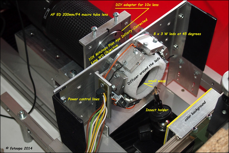
The current version contains 8 LEDs each 3W. This was more than enough to use at ISO 200 an exposure times of 15 msec. Now I would like to make a new version. The light would be distributed internally through the walls. The LEDs can not go directly to the object. There are 2 difuse zones provided. The design is planned for the Mitutoyo lenses 10X and 5X. It can also be adapted for other lenses. Here the design:

Image

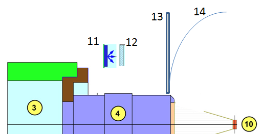
The different parts are as follows:

1 Powers leds 12 X -> problem is the right led choice.
2 Heat sink required for reduced power in continuous light live-view.
3 Tube lens, I use the AF ED 200 / F4 Nikkor macro.
4 Mitutoyo Plan Apo 10X Infinity Corrected Long WD Objective.
5. Inner ring light guide.
6 Outer ring light guide.
7 Outer snoot shape.
8 Inner snoot shape.
9. Diffuser 1 or 2 layers.
10. Object calculated for 5mm goes for 5X and 10X lenses.
11 Adapter Mitutoyo tube lens space minimal front tube lens and Mitutoyo lens.

Before I make the mechanical parts I would prefer to receive your opinions. Especially around the light channel and snoots with difuser is difficult. I can start with my existing power LEDs. In this new version I would use 12 leds. The outline is slightly larger than my existing version.

I think to use new LEDs. Newer LEDs have more power and better features. I do have problems with the selection. When I look at high CRI values, you have mostly lower color temperatures. I use RAW files, so the white ballans can be adapted. Those are 3000, 3500, 4000 and possibly even 5000 degrees. I definitely choose these individual components. You have the right characteristieken and you know what current you can use. On the camera I d'nt need a EFCS function, I control my own power LEDs. These are only turned on after the vibrations are gone. For this I use mirror-up mode and the LEDs only go on 400 msec after the shutter is fully open. So you have everything under control.

I wonder if it's important to use a max CRI value, I see versions of 90 and more. Higher CRI values ​​are generally a little more expensive but much difference. Anyway the price is not so important here. My current version had 6300 degrees and a CRI around 80 Because I like 9V LEDs, the choice is a little more limited. I always order leds directly to "Mouser", that choice is fixed. The control of the LEDs is in groups of 4 or 6. This way I can control the exposure direction.

Any proposal on the design is very welcome.

Frans.

rjlittlefield
Site Admin
Posts: 23605
Joined: Tue Aug 01, 2006 8:34 am
Location: Richland, Washington State, USA
Contact:

Post by rjlittlefield »

The design is elegant, but I worry about three things:

1. Illumination is restricted to a narrow ring around the objective. This will show as a sharp-edged ring in the spider's eyes.

2. Working distance is reduced.

3. Unnecessary loss of light (maybe not an important issue).

As an alternative, I suggest some scheme like this:

Image

where the components are
11: LED as in your setup, but pointed forward.
12: small diffuser mounted close to the LED.
13: large diffuser forming a wide ring around the front of the objective.
14: alternative for large diffuser, curved so as to wrap farther around the front of the subject.

The pattern of LEDs will not be visible to the subject if the front diffuser (13 or 14) is illuminated uniformly. The small diffusers (12) must be large enough and diffusive enough to make that happen.

--Rik

canonian
Posts: 891
Joined: Tue Aug 31, 2010 4:00 am
Location: Rotterdam, Netherlands
Contact:

Post by canonian »

Construction-wise both genius solutions.
I may add that in Rik's schema No.12 could be replaced with a frosted collimator of about 90°, to concentrate the wide 180° bundle of the PowerLED's and to spread the light over the entire area of diffusor No.13. ( hope this make sense, having some trouble translating my thoughts).

I know from experience ( see : http://www.photomacrography.net/forum/v ... c&start=13) that when using several high power LED's it is very difficult to spread this into an uniform area of light, the light is almost always piercing through several layers of diffusion and gets reflected in the specimens ommatidia, leaving a distinct pattern.
Last edited by canonian on Tue Sep 02, 2014 11:54 am, edited 2 times in total.

fotoopa
Posts: 194
Joined: Sat Dec 14, 2013 3:14 am
Location: Belgium
Contact:

Post by fotoopa »

Thaks Rik and fred!

These are beautiful recommendations! I must have a minimum diameter to place the LEDs. I thought of types such as Cree:
http://www.mouser.be/ProductDetail/Cree ... q3kdmwA%3d
These are approximately 14mm square. I can limit myself to 8 pieces. An alternative is to use SMD LEDs which are much smaller. They are more difficult to place with mechanical cooling. I would rather use the 13.35mm Cree versions. They have a lot of power.
Using collimator of about 90° is the opposite of diffuse. I have my doubts about. And there is certainly enough power when they are rotated 90 degrees. I'm going to redraw to see if the assembly can mechanically.

Frans.

canonian
Posts: 891
Joined: Tue Aug 31, 2010 4:00 am
Location: Rotterdam, Netherlands
Contact:

Post by canonian »

Sorry Frans, I was still editing my previous post while you answered yours.

If your concern is how to get high CRI leds (>95) I would like to point you to e.g http://www.elincom.nl/elektronica/high-cri-led.html and take a look at Citizen LEDs.
These are used as flashLEDs in Nokia mobiles.
You could ask your local suppliers (Mouser) if they can deliver.

fotoopa
Posts: 194
Joined: Sat Dec 14, 2013 3:14 am
Location: Belgium
Contact:

Post by fotoopa »

Thanks Fred!

I think with a CRI of 93 I already make a viable choice. If I order them at Mouser, they are here within 48 hours. I order frequently components. Other components for the power control like big elcos for the power pulse can be ordered simultaneously with. That is a big advantage.

Frans.

fotoopa
Posts: 194
Joined: Sat Dec 14, 2013 3:14 am
Location: Belgium
Contact:

Post by fotoopa »

I have the drawing adjusted for 12 LEDs. The outer diameter is 100 mm, the inner diameter 40 mm. This is an aluminum disk of 5 mm thick. This is also the cooling. The power LEDs will be the Cree versions: CXA1304-0000-000C0Y940E6. They are 13.35mm x 13.35mm. A PCB is provided with 12 holes will clamp the LEDs against the aluminum plate (not show up here). Via springs the leds will be connected to the PCB layout.
The leds data sheet can by found here:

http://www.mouser.be/ProductDetail/Cree ... 1Jq3kdmwA=

The new drawing of the led-flash unit:

Image

I can easy put multiple diffusers if necessary via spacers. The total led power is quit high and de peak current may always be higher. Live-view mode reduce this power via PWM to a save level. The most difficult is the curved diffuser. I'm looking for how I can make it and what materials is to use.

Frans.

canonian
Posts: 891
Joined: Tue Aug 31, 2010 4:00 am
Location: Rotterdam, Netherlands
Contact:

Post by canonian »

Frans wrote:The most difficult is the curved diffuser. I'm looking for how I can make it and what materials is to use.
I agree, where would you find a good diffusing material which fits your needs and has the right dimensions??
If you want to have it custom-made I think 3D printing is the best option, depending if the object can be made of any opaque material with the right characteristics.

Most of the diffuser material I use had its origins in packaging material.
This one I use as a final dome diffuser in some cases, placed nearest to the subject:

Image
Yep, that's the lid of a McFlurry, from a well-known hamburger chain :D

I remember Charlie used a 'whiffle ball", which he cut in half to create a dome diffuser:
Image

...and a polystyrene ball might also be an option:

Image


EDIT: Typo's and grammar
Last edited by canonian on Wed Sep 03, 2014 9:56 am, edited 1 time in total.

fotoopa
Posts: 194
Joined: Sat Dec 14, 2013 3:14 am
Location: Belgium
Contact:

Post by fotoopa »

canonian wrote:I always look around me to find diffuser material and it is usually found in packaging.
I'm going to go for a walk with my wife. Hobby stores are also good for that. So you can see something that is very useful. For the outer casing I would use a PVC tube. The inside I would stick with white reflective paper.
I see that there are LEDs with a color temperature of 5000 degrees and a CRI of 90. Here is an example:

http://www.mouser.be/ProductDetail/Cree ... 4qv%2fE%3d

They have 355 lumen at 400 mA and a CRI of 90. I use a pulse current of 700 mA, as a result, the light output is 355 * 1.6 = 568 lumen. With 12 LEDs this is about 6816 lumen. There can therefore be some loss through additional diffuseres without that I come in long exposure times. This leds are 9V. I would make six groups of two LEDs . With 6 groups, I can nicely choose the direction of the light. I can drive this with an 24 to 27V power supply to charge the 6 elcos in order to supply the peak current. In preview live mode the current can be reduced to less then 100 mA once the elcos are discharged.

Frans.

rjlittlefield
Site Admin
Posts: 23605
Joined: Tue Aug 01, 2006 8:34 am
Location: Richland, Washington State, USA
Contact:

Post by rjlittlefield »

This new design looks great. I definitely agree with using "found" materials for the curved diffuser, rather than trying to fabricate one.

(Random passing thought: On the other hand, there is something to be said for paper mache. I have visions of toilet paper mixed with white glue, spread thinly across a small inflated balloon and left to dry. I have no idea whether this would actually work. Probably at best it would produce strong textures.)

--Rik

fotoopa
Posts: 194
Joined: Sat Dec 14, 2013 3:14 am
Location: Belgium
Contact:

Post by fotoopa »

Thanks Rik!
Until now I used a cloth like the cooker hood filters, very porous. The thickness is approximately 1.5 - 2 mm. One side is slightly adhesive. For the straight sections I can stick them on a translucent plastic disk. Possibly I can also stick it on a curved clear plastic for the third diffuser (possibly some heat up in order to obtain the correct shape). One layer attenuated approximately 1 stop. The leds on the new design are minimum 8 x brightly. I expect about the same exposure times of around 20 msec with this 3 section diffuser.

Frans.

rjlittlefield
Site Admin
Posts: 23605
Joined: Tue Aug 01, 2006 8:34 am
Location: Richland, Washington State, USA
Contact:

Post by rjlittlefield »

fotoopa wrote:Until now I used a cloth like the cooker hood filters, very porous
One issue with cloth as a transmission diffuser is that it tends to have holes that let through some light undeflected. Some foam plastics have a similar problem. I have had the best results with paper, often just a sheet of Kleenex tissue. See the pictures HERE for some illustration.

--Rik

fotoopa
Posts: 194
Joined: Sat Dec 14, 2013 3:14 am
Location: Belgium
Contact:

Post by fotoopa »

Thanks again Rik!
I still see a lot of work to make the optimum diffuser. At first I was going to optimize my linear stage unit but now I'm going to continue to work on the LED flash unit. This should give better images. There is plenty of work for the entire autumn and winter period. A part of the electronics must also be reworked. And soon we will have to get some cycling in the Netherlands.

Frans.

fotoopa
Posts: 194
Joined: Sat Dec 14, 2013 3:14 am
Location: Belgium
Contact:

Post by fotoopa »

I'm still working on the design. The base 12 powers LEDs are defined. Only the selection of the proper color temperature has not yet been selected. To date, no one has said anything about the best color temperature choice. I think there are few who have experience with this new LEDs. On the other hand, I think the white ballans yet completely changed by the diffusers. Hence, it is probably not as important to choose the max CRI. So I would choose 5000 degrees, they give more light. Afterwards you have to define the white ballans.
My choice is temporary 12 pieces of this:
http://www.mouser.be/ProductDetail/Cree ... w7hG4qv/E=

Now I am thinking to use a LED background. There are many beautiful RGB-W power LEDs. Then I can set the background for each color. Color transitions are also possible. Each LED has 4 channels. That drive separately can compose each color. A diffuser should make the background uniform of light distribution. Less light will be needed than with the main light, seen directly facing the lens. I do not know whether anyone has done this with LEDs. I would rather do it that way instead of a display. I think timing is better to keep under control and there is no EFCS required into the camera. The color type leds are:
http://www.mouser.be/ProductDetail/Cree ... xWnB57g%3d

An outline drawing you see here:

Image

This LED assembly is a lot harder, they are the SMD versions, but I have it previously already solved even with single-sided pcb via milling work. There will have to be experimented with the optimal distance. I wonder whether there are users who work with color LEDs for the background lighting.
Each input is welcome.

Frans

rjlittlefield
Site Admin
Posts: 23605
Joined: Tue Aug 01, 2006 8:34 am
Location: Richland, Washington State, USA
Contact:

Post by rjlittlefield »

Be aware that RGB and "white" LEDs have very different spectra. Compare diagrams at http://en.wikipedia.org/wiki/Light-emit ... GB_systems versus http://en.wikipedia.org/wiki/Light-emit ... based_LEDs.

The white Cree's that you have linked are phosphor-based and have relatively continuous spectra. See page 23 of http://www.mouser.com/ds/2/90/20130621C ... 267980.pdf.

In contrast, the RGB components of the Cree XM-L's have well separated peaks, as shown on page 3 of http://www.mouser.com/ds/2/90/XLampXML_Color-274571.pdf. Probably this will be fine for background colors, but I thought I should mention the issue in case other readers consider using them for front illumination also.

--Rik

Post Reply Previous topicNext topic